Showing posts with label Suspension. Show all posts

Sunday, 30 November 2014

String Box

I thought I should post the method I used for setting up the suspension. At the rolling chassis stage I posted some stuff on setting the toe using laser alignment made from a steel ruler, a builders laser level and an assortment of straight metal edges but now the car is complete that is a bit redundant. There was another post here: Correct Ride Height where I just simply state "we string boxed the car" but didn't explain it, so here is how I did it - and continue to use it to make small adjustments.

I first learned this method at university where we had a Formula Student car. We had some fancy corner weight scales and also set the alignment using the string box method. By alignment I mean toe - how much each wheel is pointing "in" (towards the centre of the car) or "out" (away from the centre of the car) compared to the direction of travel, and the relation between each wheel.

All you need is a long bit of string, fishing wire or I use brightly coloured sewing thread, 4 axles stands and a steel rule. This guide will focus on taking the measurements rather than how to adjust it - as that will be specific to this car (although I will write that up too).

1. Camber

Before I get stuck in to measuring the alignment, with a bit of string and a ruler its unbelievably easy to measure the camber. I tied a small washer to the end of the string and taped it to the wing so it falls down the centre line of one of the wheels. This method assumes the body work covers the wheels when viewed from above. Make sure the car is settled. If I've just had it jacked up I sit on the corners then roll it back then forwards to a stop and wedge a wheel with a block of wood. Make sure the steering is centred as even a small amount of steering could pile on camber depending on the geometry.


It's pretty easy really - you take three measurements. Firstly measure the diameter of the wheel rim which in my case is 498mm. Note that the diameter of the edge of the rim will not be the diameter quoted for your wheels (i.e. 18" in this case). 498mm is 19.6 inches. 

Measure the distance from the string to the wheel rim at the top and bottom of the rim. For this wheel in the example this was 12mm at the top and 8mm at the bottom. If the top of the wheel is further away from the string than the bottom of the wheel, then this means that the wheel is leaning (cambered) inwards i.e. negative camber.


With an easy bit of trig you can then say the camber angle = inverse tan(8/498) = -0.46°. Note that the result of the calculation was positive but the top of the wheel tips in towards the centre of the car so this is negative camber. Luckily I have a digital inclinometer to check and this read -0.5°. I did this for all 4 wheels and got the following results:

FL = -0.46°         FR = -0.58°

RL = -0.23°        RR = -0.3°

For the Dax De Dion, the manual says the rear should be zero and the front should be -0.25°. The rear is set by shims which is easy to adjust and when you're done, that's it really. When I first set this up before the first drive to the IVA test, I spent a long time trying to get it perfect but the adjustment required was less than the thickness of a shim , so -0.23° and -0.3° on a target of 0° was about as close as I was going to get. Interestingly I have just referred back to some old posts at the rolling chassis stage here: Alignment and the camber was -0.1° and -0.2° rear left and rear right respectively. It seems that as everything has bedded in and a few spanner checks progressively tightening everything up has increased the camber slightly.

The front is a little harder to set up precisely on the Dax and is more like most road cars. The top of the upright is secured by two bolts in a long slot. To adjust the camber, you loosen the bolts, give the upright a tap so it slides in the slot then tighten up the bolts again. Needless to say, this is a little hit-and-miss and took ABSOLUTELY CHUFFIN AGES to get right and it seems  by the results above that over the last year and 2500 miles this has wandered out a little bit. Looking at my notes I had this at -0.3° front left and -0.35° front right but in normal driving a normal person can't possibly tell the difference between -0.3° and -0.5° camber so I probably wont bother adjusting it right now.

Next - toe measurement.

Monday, 31 March 2014

Clonking rear end - resolved

In all the engine excitement I had forgotten that I have actually resolved one of the many issues since the car has been on the road.

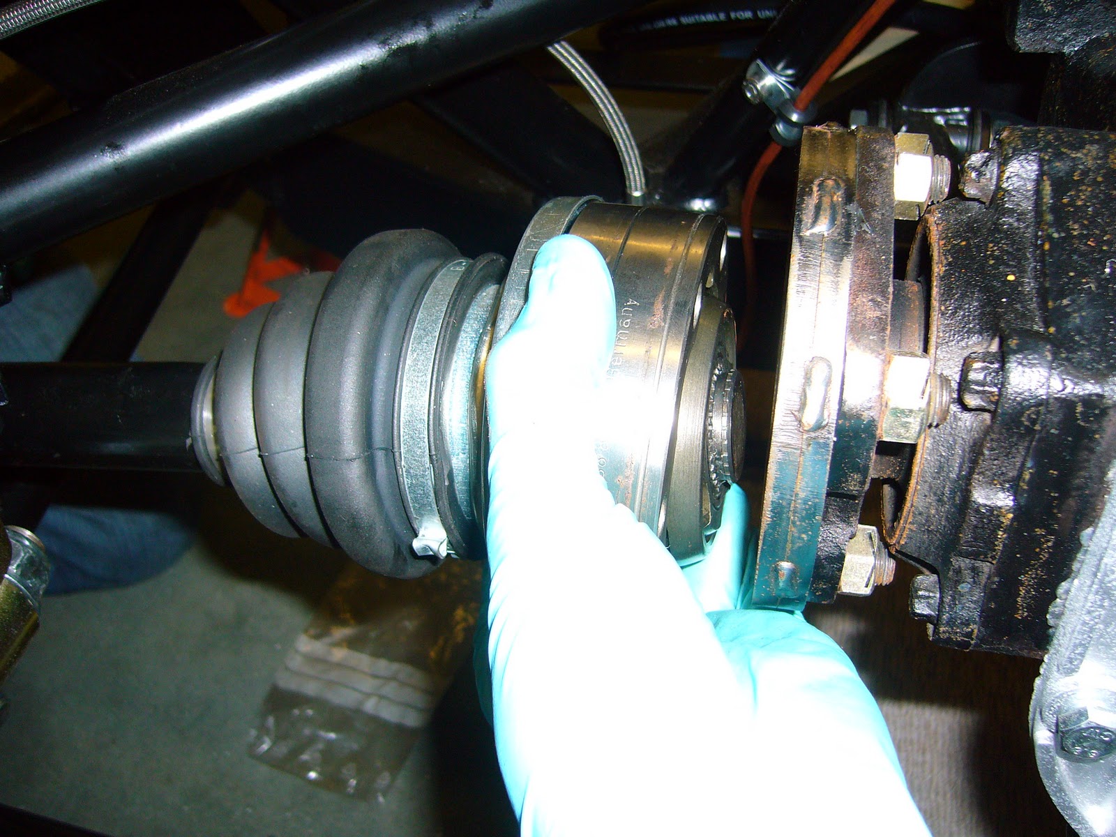
The clonking rear end when coming on/off the throttle, and clunking when reversing. I thought I had narrowed it down to CV joints but while I was under the car doing something else I thought after almost 1000 miles its probably a good idea to do a general spanner check. The suspension has been adjusted a few times so I went round everything I could see to make sure it hadn't come loose.

It turns out a few things were surprisingly loose. Bellhousing bolts for one, on the passenger side. One of them was only hand tight!

Then the big one - Diff carrier mounts. Took a FULL turn of a socket. They weren't loose, they just weren't effin' tight, which I believe is the precise torque rating required. Since nipping these up there have been NO clonks whatsoever when sharply  transitioning on/off the throttle.

A recurring theme is that every fixing which has needed nipping up has had a plain nut and spring washers. I am now of the opinion that spring washers are useless for anti-shake. One job for the future is to go round and replace any plain nut/spring washer combos for nylocs (unless its somewhere toasty hot of course). Some places like the bellhousing are a bolt into a threaded hole so there I'll leave the washers in (for clearance as otherwise I'll need shorter bolts) but will apply some loctite to the threads.

Wednesday, 6 April 2011

Alignment Finishing

Tried to attempt assembly of handbrake, discs and caliper carriers but first decided to have a last check of the toe, and borrowed a digital inclinometer from work to check camber (although its non-adjustable).

The reason for this is that although in the manual it says to set the toe/alignment off the upper forward mounting lug and then measure the space in the other 2 lugs and fill appropriately, if you were to be ±1 shim in the lower forward lug and then did up the nut effin tight you could inadvertently alter the toe and potentially the camber depending how bendy everything is.

Due to dissasembly for messing around with driveshafts, then reassemby, the aligment measurement for the rhs was out by 3mm at the front of the car which is near as damn it one thin shim (0.15mm). Maybe I wasnt quite so brutal in doing up the nut as before but anyways we were getting sick of the iterative measure-adjust-remeasure process and the manual says within 2mm either side is good enough.

With all shim packs inserted and everything done up good and tight, my toe readings were 0.5mm greater at the rear of the setup bars, giving very slight toe in, and 1mm difference at the front although the width of the laser at that distance gave another 1mm potential error margin so we reckon it was as good as it could be. Out of interest the camber measurement was -0.2° and -0.1° driver and passenger side respectively. Probably not going to get much better than that and the target is 0°.

This meant that the handbrake components could go on, followed by discs.

Sunday, 3 April 2011

Finishing off the rear end

Friday/Saturday saw the rear end almost finished apart from driveshafts. Shim packs were put in the remaining mounting positions for the rear hubs, the lower mouting hole drilled through and the outer face required some filing to get the taper washer to fit (thanks Shaun!). Re-measured the alignment all fully bolted up and it was still correct so that was a relief.

Couldnt find the driveshaft circlips so wasnt able to fit the driveshafts but did a trial fitting and got a bit confused by the fact that they seemed a bit short:


Asked on the good old forum and the CV joint there isnt fully extended and spacer rings are available to fill in the gap so I'll get those ordered. Did a test fitting of the handbrake backing plates so when the driveshaft components come I can fit everything in one go before putting the body on next weekend.

Also got a bit more tedious drilling/tapping done to secure the fore/aft brake line and battery cable which barely seems long enough but as I'm going to an isolator switch I've realised that I dont need to use the dax cable anyway, I'm going to have to re-crimp terminals eventually so wasted some £ there from poor planning.

Took the opportunity for a photo with Shaun who came round for a couple of days to help out, and Naomi too, who got away with some light gardening this weekend but has some mega drilling/tapping and riveting to do in the coming week.

Wednesday, 30 March 2011

Rear Alignment Part 2

Had a final check of the alignment and took a couple more photos to clarify the method, here is the laser level which shines forward onto the steel rule at the front end of the car -


Just shimming the upper forward mount (the one with the temporary brass bolt through in the picture below) then fill in the spaces for the other 3 mounts as required. The laser points forward with a vertical line so I can take a measurement as below:


you might just be able to see a faint red line at 450mm, its a bit obscured by the camera flash.

Rear Alignment Part 1

This is proving to be extremely time consuming and I've realised during the process I may be missing some taper washers (yet another thing a simple items list on delivery would have avoided). Cut some 700mm bar with a hole 375 from one end (as per the manual) with the longer length forward. Put one bar on each rear hub. The aim is to shim the rear-pivoting hubs so that the distance between the bars front and rear is the same. This means that the rear hubs are aligned with each other. That wasn't too difficult.

The difficulty then came maintaining that setting whilst trying to align the wheels with the rest of the car. The rear wheels may be parallel to each other, but they weren't parallel with the rest of the car.

I had removed the rear left control arm to have a look at drilling the lower mounting hole in the hub, realised I didn't have a 10mm drill bit so left it with the arm off. I then went through the alignment procedure described above without the control arm attached, which put the whole rear end on the wonk. Confused me for a good half an hour that did before I fitted the arm and could continue.

I bought a small laser level from the Homebase the other day with a magnetic base so I can  put that on one of the bars, which projects a vertical line to the front of the car. The manual then suggests to measure the distance from a good datum on the chassis, the from crosslink mount. Trusty steel rule was employed and when I did this I was amazed how far out the hubs were, even though they are presumably jigged up before welding they were dissapointingly misaligned and I had to make up the difference with a LOT of shim washers. A 0.15mm shim on the rear hub is 2mm on the front measurement and from the initial setting I had to make up over 15mm. That's nearly 5mm of shim washers on the rear end. It took a lot of iterations of changing shims/measuring to get it right.

The good thing to know after speaking to someone at Dax is that getting the measurements within 2mm is acceptable, this equates to 5 minutes toe, so giving it to a garage to do they probably wouldn't get much better. Final setup is within 1mm on the measurements, tending towards toe in which is more stable. Once the car is moving all the compliance in the system will probably mean it ends up tracking straight. Hopefully. Tyre wear will reveal how good it is.

I plan on string-boxing the car when its complete which to me seems a better method than this bar-and-sight that Dax describe in the manual.

Alignment bar fitted to rear left hub:


Rear end with alignment bars fitted to both sides. Looks a bit agricultural but it does work!


Wednesday, 2 March 2011

New upper ball joints


Lack of progress due to faulty front upper ball joints. Threads stripped on installation, correct nuts,torque, calibrated torque wrench, no clue as to what was going on. New ball joints arrived today to replace faulty ones and went on a treat. Slave wheels on the front to make it feel like even more progress

Wednesday, 2 February 2011

Inadequate length bolts


Luckily in the massive bag of assorted fixings there were some special 3/4 length nuts that I assume are specifically to fix this problem. Surely it would be simpler to provide 5mm longer bolts!

Edit - This was a running theme throughout the build. A good quote from pro cobra builder Dave Brookes - "A kit car is a collection of parts that almost fit together"

Sunday, 30 January 2011

Front Suspension 2


Brakes still do do but all springy/rocking/moving bits are fitted. Setup of toe and camber is done later with full car weight on. I've also noticed we appear to be missing a steering rack

Saturday, 29 January 2011

Front Suspension 1


At last, after numerous days painting questionable blue, front suspension is about half done

Wednesday, 19 January 2011

Mega rear assembly progress


I'll admit there is a lack of driveshafts but it can almost sit without axle stands! Just followed the build manual which is very good for the chassis build stage. Flicking through the manual, later sections are a bit woolly with sweeping statements like "fit part x" and no other explanation but that's part of the fun!

Front bits and bobs being painted waiting their turn for nuttage and boltage