Tuesday, 24 July 2012

Loom 3 - dash

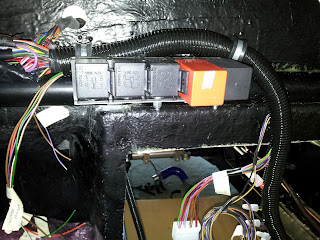
I had already fitted the relays and fuse box but I noticed whilst hunting a separate wiring problem that one of the terminals in one of the relay holders wasn't properly engaged and because of the way I had mounted them it was very difficult to get behind the relay holders to sort the terminals out. Needless to say, inspired by the good progress recently I decided to try mounting the relays again.

It used to look like this:


I modified my bodge-bracket to this:


A handy bit of door seal was used to protect the wires going to the relay holders. The finished job now looks like this:

Obviously the rest of the loom hasnt been nailed down yet, and the jumble on the left is the back of the fuse box. I just can't find a way to make it neat and tidy as there is other stuff to go in, and I'm limited by how PWS made the loom as to where things are without major loom surgery which I don't fancy doing. It still doesn't look brilliant but at least its much easier to get to the terminals for future trouble shooting.


Boot Shiny Bits 2

Small update to the last post after taking a couple more photos to show the boot lock and power to the number plate light.


Saturday, 21 July 2012

Boot Shiny Bits

Long post. A full day in the garage today and some good progress made with the boot hinges, lock and number plate light.

First of all, following the instructions in the build manual, drill holes for boot hinges.

Deviating from the build manual slightly, the dremel was then applied to the holes as I had drilled them all in the wrong place.

There we go, that's better. It took a number of fittings and re-fittings to work out that the hinges are actually handed left and right to match the curve of the body.


Boot stay sorted. Boot lip seal in (very annoying) Boot lock in, lots of dremel action. Its not quite in the centre so it will take some "adjustment" later. The loop on the boot floor had to be stood off about 6mm which is convenient as when I come to fit the carpet it can fit neatly underneath the loop. The white cable in the picture above was looped inside the boot skin when it was manufactured, to feed the number plate light. I was going to use it to draw through some other wire but it appears to be glued securely in so I pushed some heatshrink on to the end and put grommets where it goes through the skin to prevent it rubbing.


This was a bit annoying. The boot has been stood leaning against the garage wall for about a year, and over that time its bent out of shape, you can see the gap below where it doesn't follow the contour of the body.


I made the fit of the lock catch purposely very tight so you have to really push the boot down hard so it would apply stress to the boot lid and pull it back into shape. Being fibreglass, although the resin has now hardened since it was new, its still pretty flexible. The garage has been very, very hot recently meaning the resin may soften a little so I'll leave it for a few weeks and see if it permanently regains the correct shape. If that doesn't work I may have to encourage it with a heat gun.


You can see in the picture above the force from the tight fit when closed has improved it a bit so we'll see how it goes.

Sunday, 15 July 2012

Engine Bay Electrics

After finishing off the wiring in the boot, it was time to fight the bodge monster before moving on to other jobs. My original wiring for the fan relay came out a slit in the plastic tubing which was sealed up with self amalgamating tape but for the sake of £4 I got some more tee-pieces to do it properly.

All the front wiring had to come out anyway to add the washer pump wire in, which was inexplicably in the engine spur (separate to the forward loom). Also there is no earth provision in the loom for the washer pump and up above the passengers feet where the washer bottle will be, there isn't any chassis nearby to earth on to so the earth goes back into the loom and pops out the proper t-piece spur going to the fan relay. It then joins up with the fan earth to an earth point near the front near side suspension mount point. I realise that I could have wired all the earths into the loom and had one massive forward earth point but then considered single point of failure etc, and the fact that I had already drilled a load of holes and left it was it was.


The ring terminal floating on its own is from the temperature sensor, which will eventually join up with the main fan earth and the washer pump earth. Then the good old convoluted plastic tubing over the top. Another change was to put the front loom on connectors. It was straight through until the washer pump debacle and it soon became apparent that to put the nice t-piece in for the fan relay, ALL the front loom would have to come out to put it through the t-piece. Can't be bothered with that so I chopped the loom and put a connector in. Unfortunately there are 11 wires going forward and the largest connector I had was 8-way, so two 6-ways were used. Minor bodge but I can live with it. My made up excuse is redundancy.


The two wires going off on their own are power and earth for the washer pump. 

A note on protecting the wires, each crimp termination has heat shrink sleeve over it, then each bundle of wire has a pvc jacket with a further flexible convoluted tube over the top. Self amalgamating tape is copiously used at the end of each bundle was it goes into each connector.